
The American elk (Cervus canadensis) closely resembles the red deer of Europe and Asia and is now regarded by mammologists as belonging in the same species. The red deer is smallest in Scotland where it is about the size of a mule deer. But on the continent, it is larger and becomes progressively larger eastward into Asia. In Mongolia and Siberia the red deer is called the maral and is nearly the size of the American elk. In Europe, Scandinavia, and eastward, the animal we call the moose is referred to as elk. This can cause some confusion when American sportsmen are discussing trophy hunting with their European counterparts.
In North America there are three primary subspecies of elk: the American elk (Cervus canadensis spp.), which grow the largest antlers; the Roosevelt’s elk (Cervus canadensis roosevelti) of the coastal areas of the northwest, which are the largest bodied elk; and the smaller tule elk (Cervus canadensis nannodes) of the valleys of central California. These three subspecies of elk are separated by the boundary lines described in Chapter 2. The scoring of Roosevelt’s and tule elk differs from American elk, especially in regards to the treatment of “crown” points. For complete details on scoring Roosevelt’s and tule elk, refer to chapter 7.
The measurement of American elk differs significantly from Roosevelt’s and tule elk. Racks of mature typical American elk bulls normally have six normal points on each antler (including main beam tip that is counted as a normal point, but not individually measured) but, they occasionally have seven or more normal points on each antler. Non-typical American elk bulls listed in B&C’s records books have as many as 14 points per antler, but 7 to 8 points per side is the average.
In the past, American elk with skull plates that had been fractured or shattered by a bullet, dropped, etc., were not acceptable for entry in B&C. However, it is now possible to enter such trophies, so long as the pieces can be perfectly pieced back together and the spread measurements taken. Skull plates that have been sawn in half are still not eligible for entry in B&C. Each damaged skull is considered on a case by case basis. See the Shed Antlers/Split Skulls Policy on page 190 for complete details of this policy.
POINT DETERMINATION AND COUNT
American elk racks are often very symmetrical. Figure 6-A illustrates the locations of the normal and abnormal points (shaded in orange) on a typical bull’s rack. Additional normal points can arise from the top of the main beam after the normal G-6 point. Abnormal points may be present on mature bulls. Since the occurrence of bulls with abnormal points is common, a separate non-typical American elk category exists.
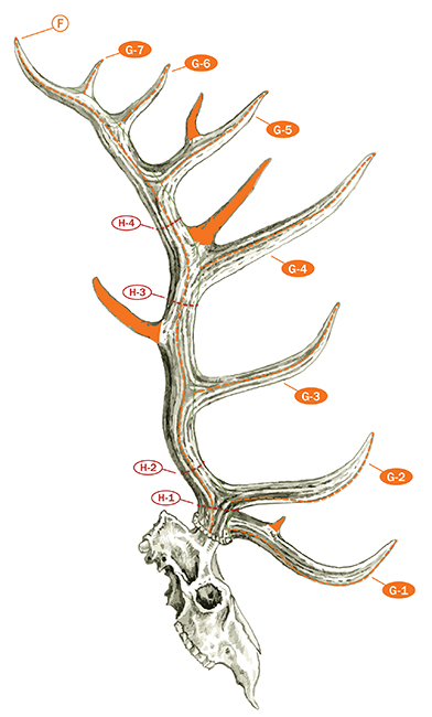
FIGURE 6-A: American elk racks are often very symmetrical with five to six normal points that grow off the main beam (F). Additional normal points can arise from the top of the main beam after the normal G-6 point. Abnormal points may be present and are indicated in solid orange shading. The circumference measurements (H) are taken at the smallest place between the normal points.
The most common location for an abnormal point on American elk is immediately above the G-4 point. These points protrude more from the top outside edge of the main beam immediately behind the G-4 point rather than directly from the top (Figure 6-B).
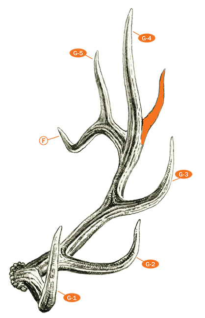
Figure 6-B: Often a mature American elk may have one or more points immediately above the G-4 that protrude more from the side of the beam than from the top making them abnormal points (shaded in orange).
As described in Chapter 3, a point is any projection at least one inch long and longer than wide at some location at least one inch from the tip of the projection (Figure 3-I, on page 28). Each projection should be measured to ascertain whether or not it is a point. Once it is determined that a projection is a point, the entire point length is measured from its tip down to its base. As illustrated on page 28, point base lines are established where the point joins either the main beam or another point. The base line should reflect the normal antler configuration as if the point was not present.
The total number of points on an antler includes the number of normal points, plus the number of abnormal points, plus the beam tips. The total number of points for each antler is recorded in the appropriate box on line A of the score chart. Point totals are supplementary data and do not add into the score.
When recording data or measurements on the score chart, it should be noted that the right and left antlers refer to the trophy’s right and left side, not the Measurer’s perspective when looking straight at the rack.
TYPICAL OR NON-TYPICAL
The first thing you need to do when you’re scoring an American elk is determine whether it should be scored as a typical or non-typical once you have identified the 6 or more normal points. In most cases it will be quite obvious. If there is any doubt, consider the number of abnormal points. If there are no or only a couple of short abnormal points, the rack should first be scored as a typical. If there are several to numerous abnormal points, use the non-typical score chart. Regardless, there is absolutely no difference in how typical and non-typical American elk are scored; all measurements are the same in both categories. The real difference between the two categories is that the total of the lengths of the abnormal points is deducted to arrive at the typical score and added in to arrive at the non-typical score.
Once you have scored a trophy, you can transfer the measurements from a typical score chart to a non-typical score chart to determine the non-typical score. If you used a non-typical score chart, you can transfer the measurements to a typical score chart to arrive at the typical score for the same trophy. In most cases, a trophy will make the minimum score in only one category. If a trophy qualifies for both categories, it is the trophy owner’s option to choose which one the trophy will be listed in as it cannot appear in both. It is strongly suggested, however, that such a trophy be listed in the category where it ranks the highest.
SPREAD MEASUREMENTS
The tip-to-tip and greatest spread measurements (Figure 6-C) are also supplementary data and are not figured into the final score. They are recorded on the score chart as they indicate the general conformation of the rack, and with the other measurements, help to give a more complete picture of antler conformation for the trophy.
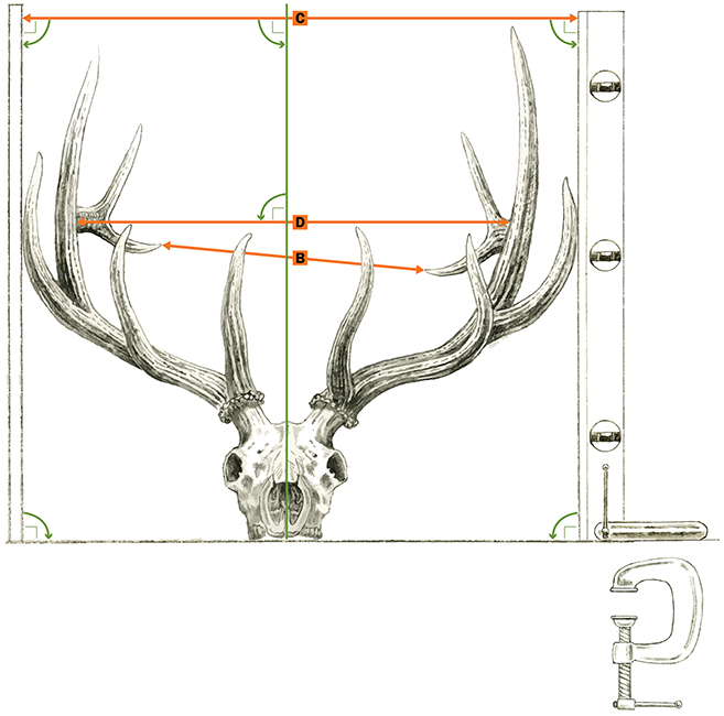
Figure 6-C: There are three separate spread measurements taken for American elk: tip-to-tip spread (B), greatest spread (C), and inside spread (D). Use a wall and a carpenter’s level with a c-clamp to create the proper right angle measurements necessary for both the greatest spread (C) and the inside spread (D). The only spread measurement that calculates into the final score is the inside spread (D), so long as it is not greater than the longer antler. If the inside spread is greater than the longer antler length, enter the longer antler length for the spread credit.
The tip-to-tip spread measurement (Figure 6-C) must be taken with a folding carpenter’s ruler or some other straightedge. This measurement is simply from the center of the tip of one antler to the center of the tip of the other. If the main beams are essentially the same length as one another, the inside spread measurement could be nearly the same width as the tip-to-tip spread if the bull’s antlers gradually (not excessively) widen. It would be an extremely rare occasion that the tip-to-tip and inside spread measurements would be exactly the same. The tip-to-tip spread is recorded in the box on line B of the score chart.
Because American elk racks are so large, the greatest spread measurement (Figure 6-C) is best taken by laying the rack on the floor against a vertical wall or some other perfectly vertical surface and sliding one of the antlers snugly against the wall so that the skull’s length is parallel to the wall. Then place a carpenter’s level, making sure that it is plumb, against the outside edge (whether it is a point tip or the main beam) of the opposite antler at the greatest distance from the wall and measure the distance from the wall to the carpenter’s level with a folding carpenter’s ruler. In no case should the human eye be relied upon for establishment of the second perpendicular line. The greatest spread is recorded in the box on line C of the score chart.
The inside spread of main beams (Figure 6-C) must be taken with a folding carpenter’s ruler, utilizing the brass extension, to complete the measurement. Care must be exercised to properly position the ruler for this measurement. The line of measurement must be at a right angle to the long axis of the skull. It must also be parallel to the skull cap. Thus, if one beam should be positioned appreciably higher than the other, it will be necessary to utilize a carpenter’s square or straightedge against the higher antler to properly locate the line. The actual measurement will reflect the greatest distance between the inside edges of the two main beams at their center, making sure to keep the measurement oriented as illustrated in Figure 6-C.
The actual measurement is taken to the inside center of the main beams once the antlers have been properly positioned. The correct points of contact for taking the inside spread measurement are illustrated in Figure 3-S on page 34. If the main beams roll inwards or tilt outwards, the inside spread is taken to the centers of the main beams as illustrated in Figure 3-S.
Rarely, one or both antlers will curve outward excessively in the vicinity of the G-4 points or near their tips (Figure 6-D). In such rare cases credit cannot be given to the elk for such abnormal spread. Thus, the inside spread measurement must be taken where the “flaring” antler(s) begins to diverge from the normal curvature or at a location below the point of divergence, whichever is greater. The inside spread of main beams is recorded in the box on line D of the score chart.
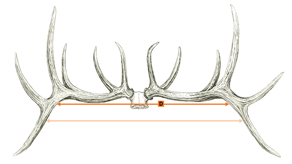
Figure 6-D: When one or both antlers curve outward excessively near their tips, the inside spread measurement (D) must be taken where the “flaring” antler(s) begins to diverge from the normal curvature or at a location below the point of divergence, whichever is greater.
Note that spread credit, also on line D of the score chart, cannot exceed the length of the longer antler main beam. If the inside spread measurement does exceed the longer main beam, record the longer main beam length (rather than the inside spread measurement) in the box on line D of the score chart for spread credit.
MAIN BEAM AND POINT LENGTHS
The length of beam and antler point length measurements are taken by the use of the flexible steel cable or a 1/4-inch wide, flexible steel clip-end tape. The use of a round, flexible steel cable (such as a modified compound bow cable available from B&C) greatly speeds up the measuring process while yielding an accurate measurement. However, only the 1/4-inch wide ring-end tape can be used for circumference measurements.
For measurement of length, the cable is positioned along the outer curve of the beam or point. The end of the measurement is marked by attaching a mini hook clip or an alligator clip to the cable at the proper spot to indicate the end of the main beam. The cable is then removed and held in a straight line against a folding carpenter’s ruler as illustrated in the General Measuring Techniques chapter to record the length measurement. The clip-end tape is often faster to use when antler points are generally straight as the clip-end can easily be hooked on the end of the antler point and the tape stretched across the point’s base line. When using a 1/4-inch wide tape on a curved point or antler beam, the Measurer will need to mark locations and pivot the tape along the line of measurement. Before marking locations, however, masking tape should be affixed to the curved points or main beams where it is necessary to make marks. The measuring tape is then rotated at these marks. Care must be exercised to align the tape at the appropriate length as each realignment is made. Never place pencil or other marks directly on the antler itself.
The length of antler main beam measurement (F) is illustrated in Figure 6-A. The measurement begins at the point where the center line of the antler along the outer side intersects the burr. This point is above and slightly off center of the eye socket. To determine this starting point, view the antlers from the side, lining up the far side with the near side. Find the middle of the burr as the antlers are viewed from this angle (i.e., the center of the burr on the outer side). It is neither at the lower front edge nor at the rear edge of the beam, but rather at the bottom outside center of the burr.
The measurement proceeds on the outer side of the beam on out to the beam tip. This line should stay in the middle of the beam on the outer side. Since the antler beams on most mature American elk tend to roll in and out along their length, it is very helpful to first draw the base lines of the normal points on masking tape. These base lines will provide reference points that help the Measurer stay in the center of the beam as it roles in and out. The line can be measured from either the bottom edge of the burr to the tip or from the tip to the bottom edge of the burr. If an abnormal point (or antler projection) is slightly in the line of measurement, simply find the shortest path around the point either above or below the projection and continue the measurement.
In rare instances, it may be necessary to use calipers to determine an accurate length of main beam measurement because of an obstructing point or growth. If this is the case, start by making a tick mark on masking tape affixed to the main beam immediately before and after the obstruction to mark the path of the main beam length through it. Then, measure the distance from the bottom edge of the burr to the first tick mark before the obstruction with a cable. Then use calipers to measure the distance between the two tick marks through the obstruction. Finish by measuring the distance from the tick mark on the opposite side of the obstruction to the beam tip with a cable. Then add all three measurements together to arrive at the length of the main beam. The length of main beam is recorded in the box on line F of the score chart.
Occasionally, the main beam tip may appear as a small bump or short point on the backside of the G-5 or G-6 point as illustrated in Figure 6-E. In such cases, the beam length is measured to the tip of the bump even though it may not qualify as a point by itself because it is the end of the main beam.
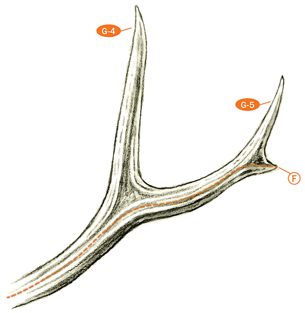
Figure 6-E: In rare cases the beam tip may not qualify as a point by itself. However, beam length (F) is still measured to the tip of the bump, and it is counted as a point in the point total for each antler.
POINTS
After the measurement of the beam lengths, the lengths of the normal points are recorded. Keep in mind the following general rules for American elk points:
- Normal points arise from the front (G-1, G-2), side (G-3), and top (G-4, G-5, etc.) of the main beam at roughly spaced intervals and are usually paired with similar length points on the other antler in a more or less symmetrical pattern.
- Any “extra” sets of matched “normal-looking” points below the normal G-4 points (Figure 6-F), other than the normal G-1, G-2, and G-3 points, are always abnormal. The fourth point, which is commonly referred to as the sword or dagger point, is still always the normal G-4 point in such cases.
- Points arising from the sides or bottom of the main beam or any normal points are always abnormal points on American elk.
- If an American elk has an unmatched G-1, G-2, G-3, or G-4 point (Figure 6-G), this point should be treated as a normal point. Its length should be entered on the score chart as a normal point and a zero or dash entered on the opposite side for the missing point. Above G-4, one cannot have an unmatched normal point on American elk unless the point is matched against one that is completely broken off or unless the unmatched point is at the end of the beam. If an unmatched point occurs between two normal points above G-4, it is treated as an abnormal (non-symmetry) point.
- While the score chart shows space for recording only seven normal points, there is no upper limit to how many normal points can occur on an American elk antler. In the extreme rarity that more than seven normal points (not including the beam tip) occur, the measurements of the extra point(s) may be included as a separate, additional line or as a separate attachment. Be sure to explain this action in the REMARKS section.
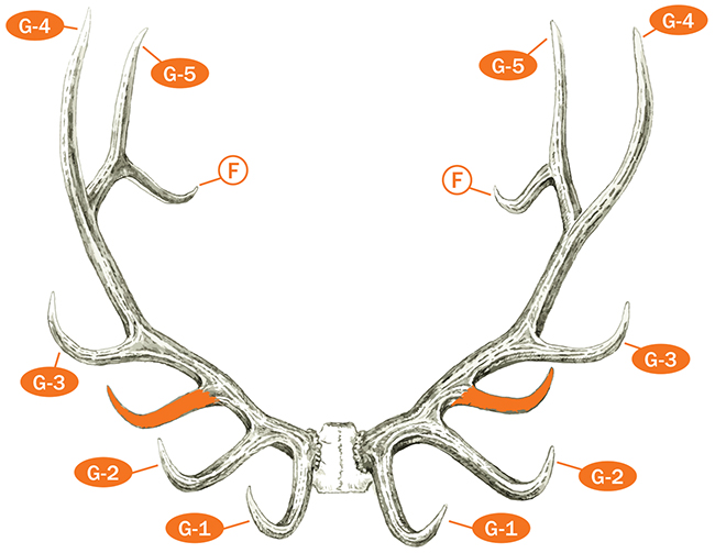
Figure 6-F: Any sets of matched points below the G-4 points, other than the normal G-1, G-2, and G-3 points, are always abnormal (shaded in orange).
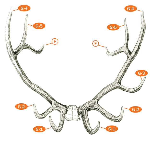
Figure 6-G: If an American elk has an unmatched G-1, G-2, or G-3 point, this point is treated as a normal point.
The lengths of the individual normal points (G-1, G-2, etc.) are recorded in the proper boxes on the score chart. Points are measured either from the base lines established on the main beam to the tip of each point or from point tip to the base line. Either method will yield the same result. Generally, points end in a sharp cone shape, with the measurement being to the tip of this cone. Should the point end in a noticeably blunted condition, somewhat like a human thumb, the measurement line can be continued to the midpoint of the rounding. If a point (or beam) is broken and not a round blunt end, use a credit card to “square off” the end of the point.
Establishment of the base lines for individual point measurement is illustrated in Figure 6-H. The base line is established to separate that material properly called main beam from the material of the point (or to separate an abnormal point from its “parent” point). Properly drawn, the base line should delineate the same amount of beam (or “parent” point) material below it as can be ascertained on either side of the point. This is especially critical in American elk as the beam often twists and decreases in diameter at some point locations. The Measurer should remain parallel with the contour of the lower edge of the beam when establishing a base line to ensure that the point base line has not cut too deeply into the main beam, which would exaggerate the length of the point.
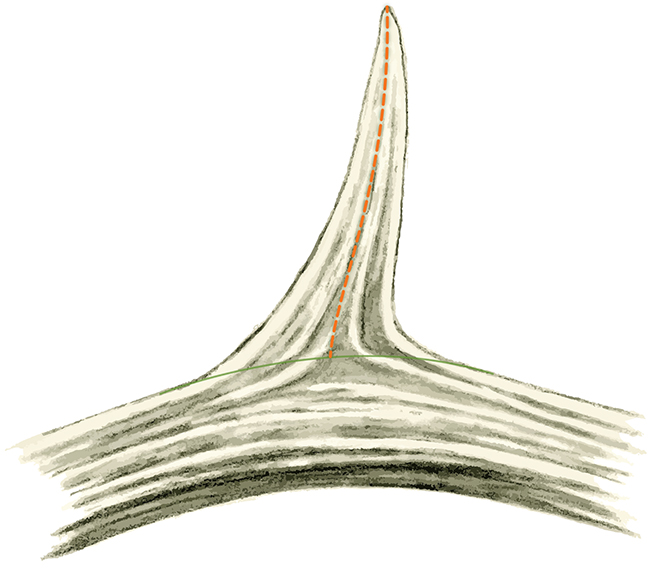
Figure 6-H: Remain parallel with the contour of the lower edge of the beam when establishing a base line (green line) to ensure that the point base line has not cut too deeply into the main beam.
Antler points are measured along the outer side of their curve. In most cases the normal points curve inward and are simply measured on the outside of the rack. But, should a point curve outward (often G-6 points will), it would be appropriate to measure it on the inside of the rack and thus reflect properly the outer curve of the point.
One item to note is the taking of the length of the G-1 point. The base line for G-1 is drawn from the top of the beam just next to the burr to the top of the beam between G-1 and G-2 on the outer side of the beam. The length of G-1 is then measured from the tip, over the curve, to the center of this point on the outer side. It is not taken over the curve to the burr! The proper line of measurement begins at the tip and proceeds over the curve of G-1 and then angles across the point to the center mark that is on the outer side as illustrated in Figure 6-I. If the G-1 point is “bent” downward rather than in the usual upward fashion, the measurement of its length is taken in the same way except now the line is coming up from the tip of the point. The same procedure of following the outer curve applies to abnormal points as well.

Figure 6-I: When measuring the G-1, the proper line of measurement begins at the tip and proceeds over the curve of G-1 and then angles across the point to the center mark of the base line that is on the outer side of the point.
CIRCUMFERENCES
Four and only four circumferences are always taken on American elk regardless of the number of normal points. The four circumferences locations (H-1, H-2, H-3, and H-4) illustrated in Figure 6-A on page 56 should only be taken with a ring-end measuring tape. The tape should be positioned in the general area of the indicated measurement by looping it around the main beam. Then pull the tape together and gently slide it back and forth along the beam until the smallest circumference measurement is obtained. If you use a clip-end tape to measure circumferences, overlap the tape at a full 10-inch increment to simplify the procedure. Be sure to subtract the amount of overlap (in this case 10”) before recording the measurement.
Unlike the deer categories where the H-1 circumference is taken at the smallest place between the burr and the G-1 point, the H-1 circumference on American elk is taken at the smallest place between the G-1 and G-2 points. Further, the H-2 circumference is taken at the smallest place between the G-2 and G-3 points; the H-3 circumference is taken at the smallest place between the G-3 and G-4 points; and the H-4 circumference is taken at the smallest place between the G-4 and G-5 points.
Occasionally there is an abnormal point that comes off the side of the main beam, out of line with the other normal points, especially between the G-4 and G-5 points on American elk. When this happens, the circumference measurements are taken at the narrowest location on either side of the abnormal point. Abnormal points cannot serve as the separation of circumference locations.
If a G-2 point is completely missing (didn’t grow) on either or both antlers, then the H-1 and H-2 circumferences are taken at the same location, the narrowest place between the G-1 and G-3 points. If the G-3 point is completely missing (didn’t grow) on either or both antlers, then take the H-2 and H-3 circumferences at the same location, the narrowest place between the G-2 and G-4 points. If a bump that does not qualify as a point occurs in the location of the normal G-2 or G-3 points, the circumference locations can be taken at the narrowest locations on either side of the bump. While we have never seen a missing G-1 or G-4 point on a mature bull that makes the minimum score, the same logic would apply for taking the H-1 and H-4 circumference measurements.
Occasionally Measurers are presented with racks where the normal points are broken off and have a length value of zero. If the G-1 is broken off, take the H-1 circumference at the normal location between the stub of the missing G-1 point and the G-2 point. If the G-2 point is broken off, take the H-1 and H-2 circumferences at the normal locations on either side of the stub of the missing G-2 point. If the G-3 point is broken off, take the H-2 and H-3 circumferences at the normal locations on either side of the stub of the missing G-3 point. If the G-4 point is broken off, take the H-3 and H-4 circumferences at the normal locations on either side of the stub of the missing G-4 point.
On the extremely rare occasion when there are only four normal points (not including the beam tip) on the antler, the H-4 circumference is taken halfway between the G-4 point and the antler tip Figure 6-J. To take this measurement properly, determine the center of the base of G-4 where it meets the main beam measurement line, then measure from this point to the beam tip. The halfway point of this line is the correct location for the H-4 circumference.
The circumference measurements (H-1, H-2, H-3, and H-4) are recorded in their appropriate boxes on the score chart.
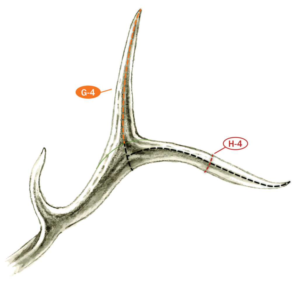
Figure 6-J: If there are only four normal points, the H-4 measurement is taken half way between the G-4 point and the antler tip.
FINAL SCORE calculations
Now that you’ve taken the last measurement, you are ready to calculate the Final Score. You start in the upper right-hand corner of the score chart by totaling the lengths of the abnormal points for the right and left antlers. If you’re calculating the Final Score for a typical bull the total of the lengths of the abnormal points in the upper right-hand corner is then moved to Line E, Column 3 where it is added into the difference column. For a non-typical bull, the total of the lengths of the abnormal points on Line E is moved to the box provided in the lower left-hand corner of the score chart.
You must then determine the differences between the beam lengths, tine lengths (G-1 through G-7), and circumference measurements (H-1 through H-4) and enter them in Column 3. You subtract the smaller measurement from the larger measurement for each line item, regardless of which side is smaller or larger, and enter the difference in the appropriate box in difference Column 3. This is followed by adding up the totals of Columns 1, 2, and 3.
You now need to turn your attention to filling in all the empty boxes in the lower left-hand corner of the score chart to calculate the Final Score for your trophy. The spread credit from line D for both typical and non-typical bulls is transposed to the blank labeled “Spread Credit” in the lower left-hand corner. Also, the totals for Columns 1 and 2 are transposed to the boxes indicted in the lower left-hand corner and added to the spread credit to come up with the subtotal.
If you are calculating the Final Score for a typical American elk, go to Final Step—Typical. However, if you’re calculating the Final Score for a non-typical American elk, go to Final Step—Non-typical.
Final Step—Typical
The total of Column 3 is now subtracted from the subtotal to arrive at the Final Score. If the Final Score for your trophy is equal to or greater than the minimum score listed at right, and you are not a B&C Official Measurer, please contact Club headquarters at 406-542-1888 or www.boone-crockett.org to get a list of a Measurers in your area.
Final Step—Non-Typical
If you are calculating the Final Score for a non-typical bull, Column 3 is subtracted from the first subtotal to arrive at a second subtotal. Add the total of the lengths of the abnormal points from Line E to the second subtotal to arrive at the Final Score. If the Final Score for your trophy is equal to or greater than the minimum score listed at right, and you are not a B&C Official Measurer, please contact Club headquarters at 406-542-1888 or www.boone-crockett.org to get a list of Measurers in your area.
 A must-have addition to the library of any hunter-conservationist, the latest edition of How to Score North American Big Game offers the most up-to-date scoring techniques with easy-to-follow instructions for scoring all 38 categories of North American big-game animals recognized by the Boone and Crockett Club with detailed explanations of the Club’s records-keeping policies and procedures. In addition the book delivers chapters on the Club’s history and its records-keeping program. The new edition also includes an expanded chapter on category boundaries enhanced with detailed, full-color maps from onXmaps.
Available online at:
www.boone-crockett.org