
Mule deer (Odocoileus hemionus hemionus), Columbia blacktail (Odocoileus hemionus columbianus), and Sitka blacktail deer (Odocoileus hemionus sitkensis) are subspecies of the same species that are separated by geographically defined boundary (Chapter 2) lines for records-keeping purposes. Antler formation is similar, with mature Sitka blacktail racks being noticeably smaller than those of Columbia blacktail, which in turn are smaller than mature mule deer. There are typical and non-typical categories for all three subspecies.
In the past, mule and blacktail deer with skull plates that had been fractured or shattered by a bullet, dropped, etc., were not acceptable for entry in B&C. However, it is now possible to enter such trophies, so long as the pieces can be perfectly pieced back together and the spread measurements taken. Skull plates that have been sawn in half still are not eligible for entry in B&C. Each damaged skull is considered on a case by case basis. See the Shed Antlers/Split Skulls policy on page 190 for complete details of this policy.
POINT DETERMINATION AND COUNT
From a structural standpoint typical mule deer and blacktails are actually the easiest of all the deer to measure as there can be no more than five specific normal points per antler, including the brow point (G-1) and the main beam tip (Figure 8-A). All other measurable points are abnormal points and so entered on the score chart.
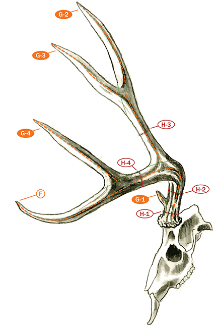 Figure 8-A: From a structural standpoint typical mule deer and blacktails are actually the easiest of all the deer to measure as there can be no more than five specific normal points per antler, including the brow point (G-1) and the main beam tip (F). The H-1 circumference is taken between the burr and first point. The H-2 and H-4 circumference measurements are taken at the smallest place between the normal points. The H-3 circumference is taken between the G-3 point and the main beam.
As described in Chapter 3, a point is any projection at least one inch long and longer than wide at some location at least one inch from the tip of the projection (Figure 3-H, page 28). Each projection should be measured to determine whether or not it is a point. Once it is determined that a projection is a point, the entire point length is measured from its tip down to its base. As illustrated on page 28, point base lines are established where the point joins either the main beam or another point. The base line should reflect the normal antler configuration as if the point was not present.
If an antler lacks a brow point (G-1), as frequently happens in mule deer/blacktail deer categories, there can be only four normal points, including the main beam tip. Sitka blacktail deer sometimes fail to develop G-3 points, and thus resemble the usual 4×4 whitetail pattern with points arising from the top of the main beam.
The total number of points on an antler includes the number of normal points, plus the number of abnormal points, plus the beam tips. The total number of points for each antler is recorded in the appropriate box on line A of the score chart. Point totals are supplementary data and do not add into the score.
When recording data or measurements on the score chart, it should be noted that the right and left antlers refer to the trophy’s right and left side, not the Measurer’s perspective when looking straight at the rack.
TYPICAL OR NON-TYPICAL
The first thing you need to do when you’re scoring a mule or blacktail deer is determine whether it should be scored as a typical or non-typical once you have identified the five normal points. In most cases it will be quite obvious. If there is any doubt, consider the number of abnormal points. If there are no or only a couple of short abnormal points, the rack should first be scored as a typical. If there are several to numerous abnormal points, use the non-typical score chart. Regardless, there is absolutely no difference in how typical and non-typical mule deer and blacktails are scored; all measurements are the same in both categories. The real difference between the two categories is that the total of the lengths of the abnormal points is deducted to arrive at the typical score and added in to arrive at the non-typical score.
Once you have scored a trophy, you can transfer the measurements from a typical score chart to a non-typical score chart to determine the non-typical score. If you used a non-typical score chart, you can transfer the measurements to a typical score chart to arrive at the typical score for the same trophy. In most cases, a trophy will make the minimum in only one category. If a trophy qualifies for both categories, it is the trophy owner’s option to choose which one the trophy will be listed in as it cannot appear in both. It is strongly suggested, however, that such a trophy be listed in the category where it ranks the highest.
SPREAD MEASUREMENTS
The tip-to-tip and greatest spread measurements (Figure 8-B) are also supplementary data and are not figured into the final score. They are recorded on the score chart as they indicate the general conformation of the rack, and with the other measurements, help to give a more complete picture of antler conformation for the trophy.
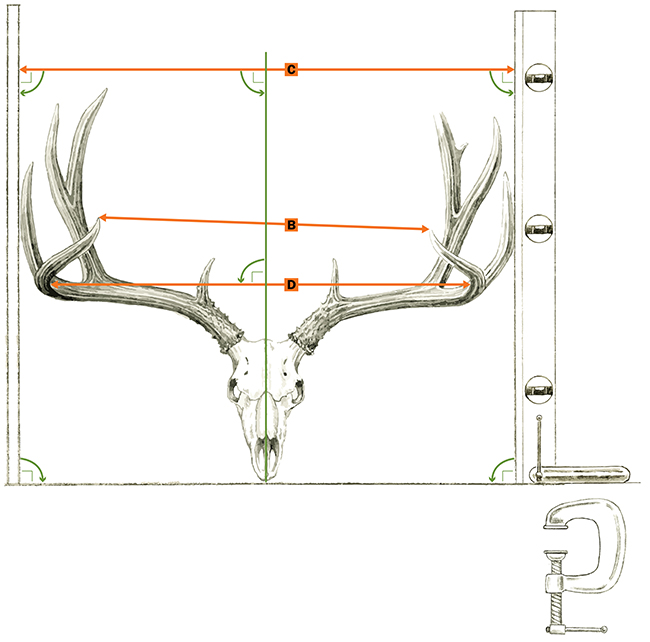 Figure 8-B: There are three separate spread measurements taken for mule deer and blacktail: tip-to-tip spread (B), greatest spread (C), and inside spread (D). Use a wall and a carpenter’s level with a c-clamp to create the proper right angle measurements necessary for both the greatest spread (C) and the inside spread (D). The only spread measurement that calculates into the final score is the inside spread (D), so long as it is not greater than the longer antler. If the inside spread is greater than the longer antler length, enter the longer antler length for the spread credit.
The tip-to-tip spread measurement (Figure 8-B, B) is taken with a folding carpenter’s ruler or some other straightedge. This measurement is simply from the center of the tip of one antler to the center of the tip of the other. On mule deer that flare out in a general fashion (not excessively divergent), the inside spread may occur near the beam tips and be nearly the same as the tip-to-tip spread measurement. The tip-to-tip spread is recorded in the box on line B of the score chart.
The greatest spread measurement (Figure 8-B, C) is best taken by laying the rack on the floor against a vertical wall or some other perfectly vertical surface and sliding one of the antlers snugly against the wall so that the skull’s length is parallel to the wall. Then place a carpenter’s level, making sure it is plumb, against the outside edge (whether it is a point tip or the main beam) of the opposite antler at the greatest distance from the wall and measure the distance from the wall to the carpenter’s level with a folding carpenter’s ruler. In no case should the human eye be relied upon for establishment of the second perpendicular line. The greatest spread is recorded in the box on line C of the score chart.
The inside spread of main beams (Figure 8-B, D) must be taken with a folding carpenter’s ruler, utilizing the brass extension, to complete the measurement. Care must be exercised to properly position the ruler for this measurement. The line of measurement must be at a right angle to the long axis of the skull. It must also be parallel to the skull cap. Thus, if one beam should be positioned appreciably higher than the other, it will be necessary to utilize a carpenter’s square or straightedge against the higher antler to properly locate the line. The actual measurement will reflect the greatest distance between the inside edges of the two main beams, making sure to keep the line oriented as illustrated in Figure 3-S on page 34.
The actual measurement is taken to the inside center of the main beams once the antlers have been properly positioned. The correct points of contact for taking the inside spread measurement are illustrated in Figure 3-S on page 34. If the main beams roll inwards or tilt outwards, the inside spread is taken to the centers of the main beams as illustrated in Figure 3-S.
Rarely, one antler will curve inward in the normal fashion, while the other will excessively flare outward. In such a case, the inside spread measurement cannot include spread caused by the excessive flaring of the antler beam. The measurement is then taken at the greatest inside spread from the location where the antler (or antlers) begins to diverge from the “normal” curvature. The inside spread of main beams is recorded in the box on line D of the score chart.
Note that spread credit, also on line D of the score chart, cannot exceed the length of the longer antler main beam. If the inside spread measurement does exceed the longer main beam, record the longer main beam length (rather than the inside spread measurement) in the spread credit box on line D of the score chart. Although the inside spread on a whitetail rarely, if ever, is greater than the length of the longer antler, this situation is fairly common in mule deer. Many non-typical mule deer display exceptionally wide spreads; thus, the Measurer must watch for this situation to occur.
MAIN BEAM AND POINT LENGTHS
The length of beam and antler point length measurements are taken by the use of the flexible steel cable or a 1/4-inch wide, flexible steel clip-end tape. The use of a round, flexible steel cable (such as a modified compound bow cable available from B&C) greatly speeds up the measuring process while yielding an accurate measurement. However, only the 1/4-inch wide ring-end tape can be used for circumference measurements.
For measurement of length, the cable is positioned along the outer curve of the beam or point. The end of the measurement is marked by attaching a mini hook clip or an alligator clip to the cable at the proper spot to indicate the end of the main beam. The cable is then removed and held in a straight line against a folding carpenter’s ruler as illustrated in the General Measuring Techniques chapter to record the length measurement. The clip-end tape is often faster to use when antler points are generally straight, as the clip-end can easily be hooked on the end of the antler point and the tape stretched across the point’s base line.
When using a 1/4-inch wide clip-end tape on a curved point or antler beam, the Measurer will need to mark locations and pivot the tape along the line of measurement. Before marking locations, however, masking tape should be affixed to the curved points or main beams where it is necessary to make marks. The measuring tape is then rotated at these marks. Care must be exercised to align the tape at the appropriate length as each realignment is made. Never place pencil or other marks directly on the antler itself.
The length of antler main beam measurement (F) is illustrated in Figure 8-A. The measurement begins at the point where the center line of the antler along the outer side intersects the burr. This point is above and slightly off center of the eye socket. To determine this starting point, view the antlers from the side, lining up the far side with the near side. Find the middle of the burr as the antlers are viewed from this angle (i.e., the center of the burr on the outer side). It is neither at the lower front edge nor at the rear edge of the beam, but rather at the bottom outside center of the burr.
Once the starting location on the burr is noted, the length of the main beam measurement proceeds along the outer side of the beam toward the middle of the antler beam below the G-2 point as illustrated in Figure 8-A. From that location, it proceeds on out to the beam tip over the outer curve of the antler. In general, this line should stay near the middle of the beam on the outer side. The line can be measured from either the burr to the tip or the tip to the burr.
Prior to making the actual measurement by either method, it is often helpful to hold the rack in a normal, upright position at arm’s length. This will show whether or not the chosen line properly follows the outer curve of the main beam.
If the antler beam rolls inward, still stay in the middle of the beam even though the middle may not be on the true outer side surface of the antler. If the beam hooks upward, still stay on the outer side of the antler near the middle (and not over the curve of the upper hook which would place the measurement line along the bottom of the beam). If an abnormal point (or antler projection) is slightly in the line of measurement, simply find the shortest path around the point either above or below the projection and continue the measurement.
In rare instances, it may be necessary to use calipers to determine an accurate length of main beam measurement because of an obstructing point or growth. If this is the case, start by making tick marks on masking tape affixed to the antler immediately before and after the obstruction to mark the path of the main beam length through it. Then, measure the distance from the bottom edge of the burr to the first tick mark before the obstruction with a cable. Then use calipers to measure the distance between the two tick marks through the obstruction. Finish by measuring the distance from the tick mark on the opposite side of the obstruction to the beam tip with a cable. Then add all three measurements together to arrive at the length of the main beam. The length of main beam is recorded in the box on line F of the score chart.
After the main beam lengths are recorded, the lengths of G-1, G-2, and G-4 points are measured from their base lines on the main beam. The base line for the G-3 point is along the front edge of the G-2 point from which it arises. Points that arise from the outside or inside edges of the G-2 point are always abnormal points. Since a point is measured over its outer curve, the baseline can be on either the inside or the outside of the rack depending on the curvature of the point.
POINTS
The designation of points as either normal or abnormal requires some judgment, especially if there are numerous paired points. Figure 8-C illustrates some abnormal configurations. Keep in mind the following general rules for mule and blacktail deer points:
- Burr tines or “beauty points” (points arising from or near the antler burr) are always abnormal.
- Split or multiple brow tines mean that only one of these can be measured as the normal brow point. If one of these is a clear-cut branch of the other, the branch is designated as abnormal. If both are separate points, without one being a branch off the other, choose as the normal G-1 point the one that best matches in shape and location usual G-1 points and the G-1 point on the other antler. Generally this will be the longer point; the other(s) is then measured as abnormal.
- When a cluster of projections and points are present, for example on the G-1 point, the following rule should be applied. In order for more than one projection to be treated as a point, each projection separately must meet the definition of a point (longer than wide at one inch or more of length). In such cases, the base of secondary projections may be back to the main beam only if they share a common base, or back to the “parent” point if they do not.
- Except for the G-3 point, point branches (those arising from points rather than the main beam) are always abnormal.
- Points arising from the sides, top inside edge, or bottom of the main beam are always abnormal.
- Normal points occur in the “Y” branching pattern (dichotomous), with two such forks (G-2 and G-3; G-4 and beam tip) comprising the normal condition.
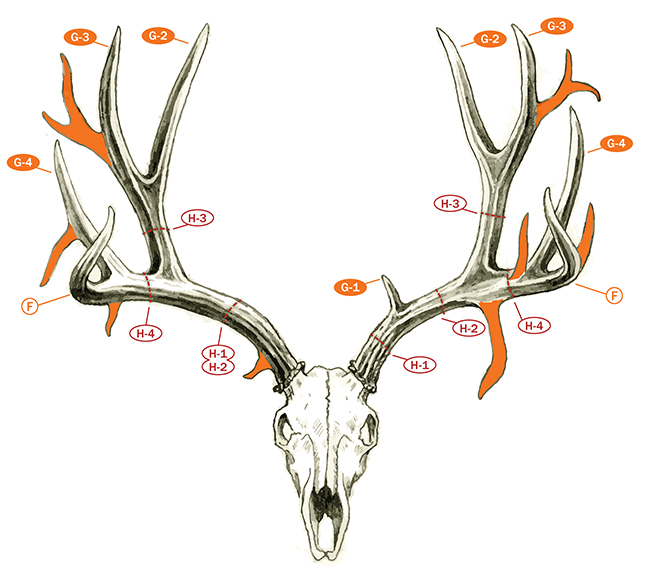 Figure 8-C: Example of abnormal point configurations for mule deer and blacktail shown in shaded orange.
The lengths of the individual normal points (G-1, G-2, etc.) and also any abnormal points present are recorded in the proper boxes on the score chart, with zero or a dash being recorded for the obvious absence of a normal point in the normal sequence. Points are measured either from the base lines established on the main beam to the tip of each point or from the point tip to the base line. Either method will yield the same result. Generally, points end in a sharp cone shape, with the measurement being to the tip of this cone. Should the point end in a noticeably blunted condition, somewhat like a human thumb, the measurement line can be continued to the midpoint of the rounding. If a point (or beam) is broken and not a round blunt end, use a credit card to “square off” the end of the point. In measuring points, the measurement line should be along the outer curve of the point to properly record its greatest length. Abnormal points are measured in exactly the same manner as normal points.
If a rack has numerous points and/or many abnormal points, measurement can be aided by marking each point with bits of colored tape to designate normal points (e.g., green tape) and abnormal points (e.g., red tape). A third color (e.g., yellow tape) can be used to indicate projections that do not qualify as points so that they are not inadvertently and incorrectly measured or counted as points. As each qualifying point is measured to its proper base line and recorded on the score chart, the tape is removed to show that the point has been measured. When all tape bits have been removed, the measurement of individual points is complete (remember, a main beam tip is not measured as an individual point because its length is recorded as length of main beam.)
When measuring non-typical entries, it is very helpful to record the abnormal points in a systematic fashion. Start with the burr and measure each abnormal point along the main beam to G-1; then measure all abnormal points from G-1 to G-2; then measure all abnormal points off G-2 (and G-3). Continue along the main beam and G-4 until you have recorded all abnormal points on that side of the antler. If you inadvertently fail to measure one point, it will be far easier to determine which point is missing if you have proceeded in this orderly manner.
Establishment of the base lines for individual point measurement is straightforward. The base line is established to identify that material properly called main beam from the material of a point or separate a point branch (G-3 or abnormal point) from its “parent” point. Prior to marking base lines, affix masking tape to the areas where the bases will be drawn. Properly drawn, the base line should delineate the same amount of beam (or “parent”) material below the point’s center as can be ascertained on either side of the point being measured. A good method of marking base lines is to pull a measuring cable across the point base resting on top of the parent structure antler material. Then the base line is marked on the masking tape with a pencil along the lower edge of the cable.
Antler points are then measured along the outside of their curve. In almost every case, the points G-2, G-3, G-4, curve inward and not outward. If a point should curve outward, it would be appropriate to measure it on the inside of the rack and thus reflect properly the outer curve of the point. In the case where it is not obvious which direction the point curves, measure both sides and record the longer measurement as the point length. It is never correct to measure along the edges of a point to determine its length. The same procedure of measuring points on the outside of their curve applies to abnormal points as well.
The brow tines, although usually straight, may be curved either backward or forward. If they are curved forward, they are measured on the backside in order to reflect the outer curve of the point. If they are curved backward, they are measured on the front side, again to reflect the outer curve. Note such actions in the REMARKS section.
Some Columbia blacktail, Sitka blacktail, and rarely mule deer will be missing a G-3 point on one antler and will display an apparent reversal of the usual pattern of the G-2 and G-3 points on the other. Normally, the third point (G-3) projects forward and to the outside from G-2. In some cases, the shorter branch point will project backwards as Figure 8-D displays. In such a case, if the rearmost point is designated as G-2 (as is normally done), the resulting pairing with the other antler will match this short point with the longer G-2 of the other side. Except for this reversal, the rack may be very symmetrical and matching the long G-2 with the short, “reversed” point would produce a large deduction. In such cases (one where the G-3 point is missing on one side and where the rear point on the other is a shorter branch), it is permissible to label the rear pointing projection as G-3, which will better pair the two longer points that come off the main beam. It is important to note this ruling applies only when a G-3 point is missing from only one of the antlers. If the deer has G-2 and G-3 points present on both antlers, then the rear, inner points are always G-2 and the forward projecting, outer points are always G-3 regardless of their configuration.
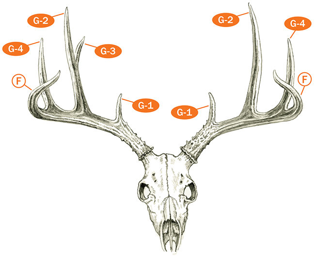 Figure 8-D: Some Columbia blacktail, Sitka blacktail, and rarely mule deer will be missing a G-3 point on one antler and will display an apparent reversal of the usual pattern of the G-2 and G-3 points.
While most mule deer display the standard five by five antler configuration, some added problems may arise. Sometimes a projection that appears at first glance to be the G-4 point may actually project from the G-2 point (Figure 8-E) instead of the main beam, as it should. When this antler configuration occurs, there is no G-4 point and the point off G-2 is treated as abnormal. This ruling will also affect the location of the H-4 circumference measurement. Some mule deer may have common base G-2 and G-4 points. If this occurs only on one side of the rack, there is no problem and the points (G-2 and G-4) are measured to the beam (Figure 8-F, left). If the G-2 and G-4 points on both antlers are common base, their lengths (on both sides) are taken as illustrated in Figure 8-F, right. This procedure is the same as the method for common base points described in the General Measuring Techniques chapter of this manual.
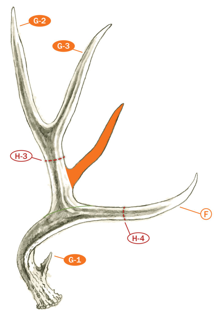 Figure 8-E: Sometimes a projection that appears at first glance to be the G-4 point may actually project from the G-2 point instead of the main beam, as it should. When this occurs, there is no G-4 point and the point off G-2 is treated as abnormal (shaded in orange).
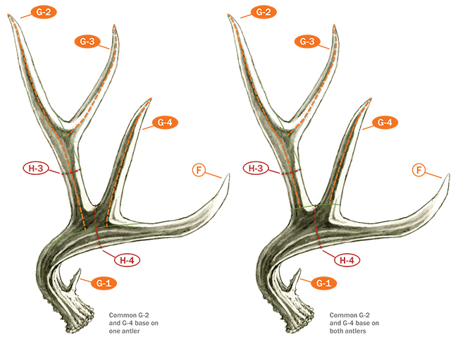 Figure 8-F: Some mule deer will have common base for the G-2 and G-4 points. If this occurs on only one antler, the point lengths are measured all the way to the beam (left). If the common base occurs on both antlers, the point lengths are measured to the base line as illustrated on the right.
CIRCUMFERENCES
Four and only four circumferences are always taken on mule deer and blacktail deer regardless of the number of normal points. The four circumference locations (H-1, H-2, H-3, and H-4) illustrated in Figure 8-A should only be taken with a ring-end measuring tape. To take the circumference measurements on mule deer and blacktails, the ring-end tape should be positioned in the general area of the indicated measurement by looping it around the main beam or the G-2 point. Then pull the tape together and gently slide it back and forth along the main beam until the smallest circumference measurement is obtained.
The H-1 circumference is taken at the narrowest place between the burr and the brow tine (G-1); the H-2 circumference is taken at the narrowest place between the G-1 and G-2 points; the H-3 circumference is taken on the G-2 point at the narrowest place between the main beam and the G-3 point; and the H-4 circumference is taken at the narrowest place between the G-2 and G-4 points. If you use a clip-end tape to measure circumferences, overlap the tape at a full 10-inch increment to simplify the procedure. Be sure to subtract the amount of overlap (in this case 10”) before recording the measurement.
If the G-1 point is completely missing (didn’t grow) then H-1 and H-2 are taken at the same location (Figure 8-G), the smallest circumference between the burr and the G-2 point. However, if there is an indication (bump) of the presence of the G-1 point even though the projection does not qualify as G-1 then it is proper to take the H-1 and H-2 circumference measurements on either side of the projection, as would normally be done if it was a point.
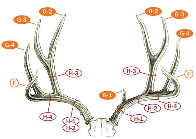 Figure 8-G: If the G-1 is missing, take both the H-1 and H-2 circumference measurements in the same location.
Some blacktails (rarely mule deer) fail to develop the (G-3) point that branches from G-2, thus lack the usual point of location for the third circumference (H-3). In such a case, measure the G-2 point length and then mark its midpoint as the proper location to take the H-3 circumference (Figure 8-H). If the G-4 point is totally missing, the H-4 circumference is taken on the main beam halfway from the center point of the length of the G-2 point to the tip of the main beam (Figure 8-I). To make this measurement properly, determine the center of the base of the G-2 point where it meets the main beam and draw a line from that point across the main beam perpendicular to the axis of the main beam. Then measure the distance from that perpendicular line to the beam tip. The halfway point of measurement is the correct location for the H-4 circumference.
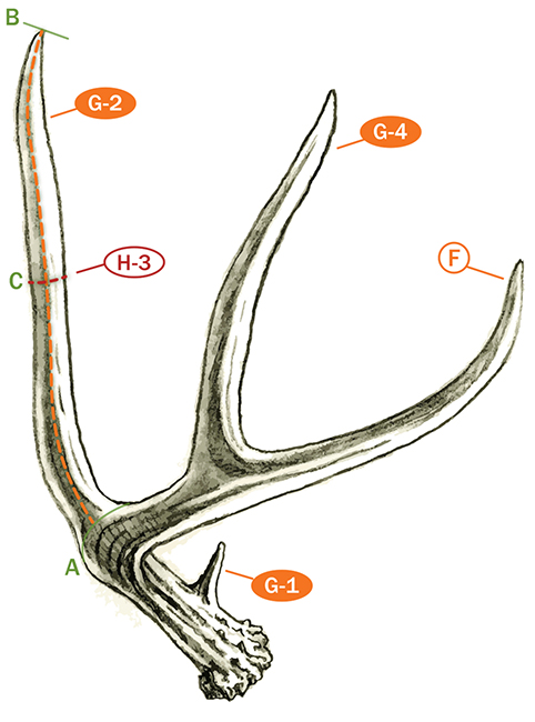 Figure 8-H: Some blacktails (rarely mule deer) fail to develop the third point (G-3) branching from G-2, thus lack the usual point of location for the third circumference (H-3). In such a case, measure the G-2 point length and then mark its midpoint as the proper location to take the third circumference.
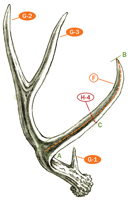
Figure 8-I: If the G-4 point is missing, attain the proper location for the H-4 circumference by extending the center of the G-2 base line down (A) and measuring from that point to the main beam tip (B) and divide in half (C) and mark as the location to take the H-4.
Occasionally Measurers are presented with racks where the normal points are broken off and have a length value of zero. If a normal G-1 point is broken off, take the H-1 and H-2 circumferences in the usual locations on either side of the stub of the G-1 point. If the G-3 point is broken off, the H-3 circumference should be taken at the narrowest place between the main beam and the stub of the broken off G-3 point. Finally, if the G-4 point is broken off, the H-4 circumference is taken at the narrowest place between the G-2 point and the stub of the broken off G-4 point.
Occasionally, an abnormal point may arise between normal points. When this happens, the circumference measurements are taken at the narrowest location between normal points on either side of the abnormal point. Abnormal points cannot serve as the separation of circumference locations.
The circumference measurements (H-1, H-2, H-3, and H-4) are recorded in their appropriate boxes on the score chart.
FINAL SCORE CALCULATIONS
Now that you’ve taken the last measurement, you are ready to calculate the Final Score. You start in the upper right-hand corner of the score chart by totaling the lengths of the abnormal points for the right and left antlers. If you’re calculating the Final Score for a typical buck the total of the lengths of the abnormal points in the upper right-hand corner is then moved to Line E, Column 3 where it is added into the difference column. For a non-typical buck, the total of the lengths of the abnormal points on Line E is moved to the box provided in the lower left-hand corner of the score chart.
You must then determine the differences between the beam lengths, tine lengths (G-1 through G-4), and circumference measurements (H-1 through H-4) and enter them in Column 3. You subtract the smaller measurement from the larger measurement for each line item, regardless of which side is smaller or larger, and enter the difference in the appropriate box in difference Column 3. This is followed by adding up the totals of Columns 1, 2, and 3.
You now need to turn your attention to filling in all the empty boxes in the lower left-hand corner of the score chart to calculate the Final Score for your trophy. The spread credit from line D for both typical and non-typical bucks is transposed to the blank labeled “Spread Credit” in the lower left-hand corner. Also, the totals for Columns 1 and 2 are transposed to the boxes indicted in the lower left-hand corner and added to the spread credit to come up with the subtotal.
If you are calculating the Final Score for a typical buck, go to Final Step—Typical. However, if you’re calculating the Final Score for a non-typical buck, go to Final Step—Non-typical.
Final Step—Typical
The total of Column 3 is now subtracted from the subtotal to arrive at the Final Score. If the Final Score for your trophy is equal to or greater than the minimum score listed at right, and you are not a B&C Official Measurer, please contact Club headquarters at 406-542-1888 or www.boone-crockett.org to get a list of a Measurers in your area.
Final Step—Non-Typical
If you are calculating the Final Score for a non-typical buck, Column 3 is subtracted from the first subtotal to arrive at a second subtotal. Add the total of the lengths of the abnormal points from Line E to the second subtotal to arrive at the Final Score. If the Final Score for your trophy is equal to or greater than the minimum score listed at right, and you are not a B&C Official Measurer, please contact Club headquarters at 406-542-1888 or www.boone-crockett.org to get a list of Measurers in your area.
 A must-have addition to the library of any hunter-conservationist, the latest edition of How to Score North American Big Game offers the most up-to-date scoring techniques with easy-to-follow instructions for scoring all 38 categories of North American big-game animals recognized by the Boone and Crockett Club with detailed explanations of the Club’s records-keeping policies and procedures. In addition the book delivers chapters on the Club’s history and its records-keeping program. The new edition also includes an expanded chapter on category boundaries enhanced with detailed, full-color maps from onXmaps.
Available online at:
www.boone-crockett.org